
Object tracking is often reduced to recording the trajectory of the center of mass, and there is a simple reason for this: one only needs to compute the mean values of the horizontal and vertical indexes of the pixels, which is easy and fast. But what if one wants to track the object's orientation ? To do this, my favorite method is a simple and elegant approach involving image moments.
In general, one can define an infinity of moments for any solid object in any dimension, which captures interesting features of the object. One can think of them as a generalization of the center of mass, which coordinates are the first-order moments. In images, the second-order moments can be used to determine the equivalent ellipse of an object, from which one can extract the orientation of the major and/or minor axes. That's what we are going to put into practice and discuss in this post.
A little math
Image moments are defined as weighted averages of the image pixels' intensities. In a greyscale image with pixel intensities $I(i,j)$, the raw $(p,q)$-moment $M_{p,q}$ is given by:
$$M_{p,q} = \sum_{i}\sum_{j} i^p j^q I(i,j)$$As explained in the discussion below, the moments of greyscale images heavily depend on the contrast and are thus much more difficult to interpret. So we will restrain ourselves in the sequel to binary images, where objects are made of ones and the background is zero. For a binary image the $(p,q)$-moment $M_{p,q}$ thus reads:
$$M_{p,q} = \sum_{i,j~\in~Obj} i^p j^q$$The zero-order moment $M_{0,0}$ gives the total number of pixels in the object, i.e. the object's area. The first-order moments $M_{1,0}$ and $M_{0,1}$, when normalized by $M_{0,0}$ give the coordinates of the barycenter in the horizontal and vertical directions, respectively:
and
This is where things start to be a little complicated: extracting the parameters of the equivalent ellipse from the second-order moments $M_{2,0}$, $M_{1,1}$, and $M_{0,2}$ is not as immediate since one have to use the second-order central moments, which differ from the second-order raw moments. Here they are:
The covariance matrix of the binary object is:
$$cov(Obj) =\begin{bmatrix}\mu_{2,0}' & \mu_{1,1}'\\\mu_{1,1}' & \mu_{0,2}'\end{bmatrix}$$and the eigenvectors of this covariance matrix correspond to the major and minor axes of the equivalent ellipse. Here are the final formulae giving the major axis orientation $\theta$ and the major and minor axis lengths $l$ and $w$, respectively:
$$\theta = \frac{1}{2}.tan^{-1} \left( \frac{2\mu_{1,1}'}{\mu_{2,0}'-\mu_{0,2}'} \right)$$ $$ l = \sqrt{8 \left( \mu_{2,0}' + \mu_{0,2}' + \sqrt{4\mu_{1,1}'^2 + (\mu_{2,0}'-\mu_{0,2}')^2} \right)}$$ $$ w = \sqrt{8 \left( \mu_{2,0}' + \mu_{0,2}' - \sqrt{4\mu_{1,1}'^2 + (\mu_{2,0}'-\mu_{0,2}')^2} \right)}$$And here we are!
Warning! One of the research articles that present this calculation (and actually the one that brought my attention onto this method for image analysis) is Image Moments-based Structuring and Tracking of Objects by L. Rocha, L. Velho and P.C.P. Calvalho (2002). Unfortunately the formulas for $l$ and $w$ have a typo in this paper, with factors 6 instead of 8. This does not change a lot the resulting ellipses, but it's always better to use the right formulas so take the ones presented here, they've been double-checked and extensibily tested in many occasions.
Now that we have all the theoretical tools, let's pass on to practice.
Let's compute it !
A package containing optimized Matlab functions for computing and displaying the equivalent ellipse is provided at the end of this post.
Here is the code for the main function
function E = get_ellipse(Img, direct)
%GET_ELLIPSE Equivalent ellipse of an image
% E = IM.GET_ELLIPSE(IMG) finds the equivalent ellipse of an image IMG.
% IMG is a n-by-m image, and E is a structure containing the ellipse
% properties.
%
% E = IM.GET_ELLIPSE(..., false) will not try to assign a
% direction based on the third moment. The orientation of the object will
% be unchanged but the direction is pi-undetermined.
%
% See also: IM.draw_ellipse
% --- Default values
if ~exist('direct', 'var')
direct = true;
end
% --- Computing moments
% Object's pixels coordinates
I = find(Img);
[j, i] = ind2sub(size(Img), I);
% Function handle to compute the moments
moment = @(p,q) sum((i.^p).*(j.^q).*double(Img(I)));
% --- Prepare the output
E = struct();
% --- Get the Moments
E.m00 = moment(0, 0);
E.m10 = moment(1, 0);
E.m01 = moment(0, 1);
E.m11 = moment(1, 1);
E.m02 = moment(0, 2);
E.m20 = moment(2, 0);
% --- Ellipse properties
% Barycenter
E.x = E.m10/E.m00;
E.y = E.m01/E.m00;
% Central moments (intermediary step)
a = E.m20/E.m00 - E.x^2;
b = 2*(E.m11/E.m00 - E.x*E.y);
c = E.m02/E.m00 - E.y^2;
% Orientation (radians)
E.theta = 1/2*atan(b/(a-c)) + (a<c)*pi/2;
% Minor and major axis
E.w = sqrt(8*(a+c-sqrt(b^2+(a-c)^2)))/2;
E.l = sqrt(8*(a+c+sqrt(b^2+(a-c)^2)))/2;
% Ellipse focal points
d = sqrt(E.l^2-E.w^2);
E.x1 = E.x + d*cos(E.theta);
E.y1 = E.y + d*sin(E.theta);
E.x2 = E.x - d*cos(E.theta);
E.y2 = E.y - d*sin(E.theta);
% Ellipse direction
if direct
tmp = [i-mean(i) j-mean(j)]*[cos(E.theta) -sin(E.theta) ; sin(E.theta) cos(E.theta)];
if skewness(tmp(:,1))>0
% Fix direction
E.theta = mod(E.theta + pi, 2*pi);
tmp = [E.x1 E.y1];
% Swap F1 and F2
E.x1 = E.x2;
E.y1 = E.y2;
E.x2 = tmp(1);
E.y2 = tmp(2);
end
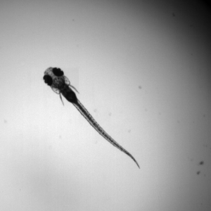
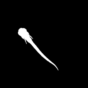
end Let's try this function. Here is a sample image of a zebrafish larva:
and let's use the
Img = imread('ZF_binarized.png')>0;    % Load binarized image and conversion uint8 → boolean
E = IM.get_ellipse(Img)                % Compute the equivalent ellipse

E =

      m00: 4803
      m10: 741932
      m01: 992957
      m11: 164543237
      m02: 217746549
      m20: 125261708
        x: 154.4726
        y: 206.7368
    theta: 0.8259
        w: 15.0856
        l: 119.2181
       x1: 234.6394
       y1: 293.6774
       x2: 74.3058
       y2: 119.7963
The orientation $\theta$ of the major axis is given by
imshow(Img)
hold on
IM.draw_ellipse(E, 'color', 'm') 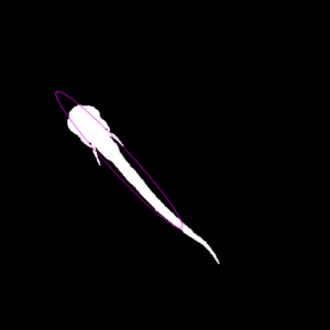
Determine the direction of asymetric objects
OK, we have the orientation, but what if we want the direction ? With an object that is asymetric with respect to the minor axis of it's equivalent ellipse, it makes sense and with our exemple we may want to track, say, the direction of the head. But if we stick onto the second-order moments, the angle $\theta$ is defined between $-\pi$ and $\pi$ and there is an indetermination here:
To correct for this, one can use the third moments, which contains information about "how asymetric" the object is. The easiest way to use the third moments here is to rotate the object around it's center of mass to make the major axis horizontal and compute the skewness of the new horizontal coordinates. A positive (resp. negative) skewness indicates that the point are more grouped on the left (resp. right) side. This property is implemented in the
Here is the result:
Application: readout of a dial needle gauge movie
Imagine we want to extract the values of the needle gauge in the following movie:
At first sight, it looks like a tough task, especially when one considers that the video is of quite low quality (look at it fullscreen) and that there is an important translational motion due to vibrations. However, this is an easy task for image moments.
In a few lines of code we can load the movie, extract and binarize the red layer and compute the equivalent ellipse:
% --- Open the video and read it frame by frame
M = VideoReader('gauge_raw.mp4');

while M.hasFrame

    % Read frame
    Img = M.readFrame();

    % Extract red layer
    Red = Img(:,:,1)-Img(:,:,3);

    % Threshold and keep only the largest object
    Tmp = bwlabel(Red>50);
    Hc = histcounts(Tmp(:));
    [~, k] = max(Hc(2:end));
    BW = Tmp==k;

    % Get the equivalent ellipse
    E = IM.get_ellipse(BW);

    % Display
    clf
    hold on
    imshow(Img);
    IM.draw_ellipse(E, 'color', 'w');
    drawnow
end
... and shazam ! Here is the result:
Then, we just have to convert the ellipse angle to a RPM value and we obtain the following signal:
Discussion
Speed. Algorithms based on image moments are fast, very fast. So fast that it can be implemented without further tweaking in live tracking algorithms, even at high framerates. For instance we have used it in the lab to track the tail beats of zebrafish larvae, and it was running flawlessly in real-time at 200Hz with Matlab and at 500Hz in C++ (image size 256x256 pixels, regular workstation).
We took benefit of the speed of this algorithm in this article, where a fast feedback loop was implemented to make a 2D virtual reality setup.
Binary or greyscale images ? The definition of image moments is also valid for greyscale images, so one can imagine to get rid of the binarization step an directly use the full image information. However, though this is possible in theory, in practice there is an important pitfall.
The problem is that every non-zero pixel contributes to the moments. Worse: the higher the moment the highest the powers and the relative weight of the bakcground increases non-linearly. To understand this effect better, let's take a binary image and continuously change the value of the background from 0 to 1:
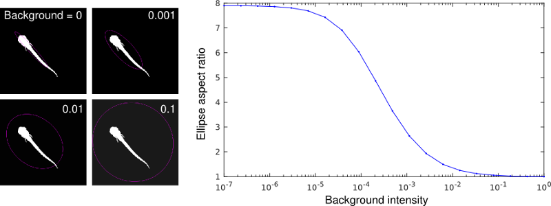
For a perfect contrast, the ellipse is well-defined and has an aspect ratio $w/l$ close to 8. As the contrast decreases, the aspect ratio steeply drops and is already at half the maximum value for a contrast of 1000:1, a value hardly ever reached in pratice.
Clearly, the contrast between the background and the object plays a critical role in the ellipse determination. Switching to binary images, i.e. forcing a perfect contrast, may reduce the information in the image but is a quasi-prerequisite of the method. And as the method gives very nice result with binary images, this is not such a big price to pay.
Downloads
Matlab: Image Moments (ZIP)
Have fun !
Comments
Dear Stefan, Indeed, the regular definition of the skewness is based on the third central moment μ3 (divided by the third power of the mean values, σ3) for samples in one dimension. When dealing with 2D objects like pixels, there are four third-order central moments (μ03, μ12, μ21 and μ30) and it is not easy to define the skewness based on these four quantities. So the convenient way I propose is to get back to the 1D case by projecting the pixels onto the major axis of the equivalent ellipse, which is defined by the second order moments, an then compute the skewness the regular way on this projected dataset. Regards,
First of all, this is super helpful. Thank you! I am doing something similar with C Elegans nematodes, but this issue I have with tracking direction is that the worm is fairly symmetric, unlike the zebrafish above. Any suggestions for how I might extend what you've done here, but adjust for tracking direction in a symmetric object?
Thanks for your nice comment. Unfortunately if the object is truly "symmetric", like a worm imaged with a low number of pixels, there is no way to determine a direction from a single image. I believe your two only options are 1) to zoom in sufficiently on the animal and have enough pixels to determine which side is the head and 2) track the animal and use the direction of motion as an indicator of the head. From my limited knowledge of C. Elegans this may be difficult since they usually swarm back and forth.
Hey I've a question to your article "Tracking object orientation with image moments ". I use this code in my thesis and it very useful thank you , I want a reference (from paper or book) for the equations of x and y used in draw ellipse. Thank you very much and best regards
Unfortunately I don't have a reference for these equations, I calculated and implemented it myself and I have not published this explicitly. But I think it can be safely considered too straightforward to justify a reference. Best regards
Hey I've a question to your article "Tracking object orientation with image moments ". You said that the angle θ is defined between −π and π and therefore you have to use the third moments. But I don't understand this: "The easiest way to use the third moments here is to rotate the object around it's center of mass to make the major axis horizontal". What do you mean with the "major axis" and isn't the skewness defined with the moment μ03? Thank you very much and best regards Stefan